What Makes an NDT Scanner Field-Ready?
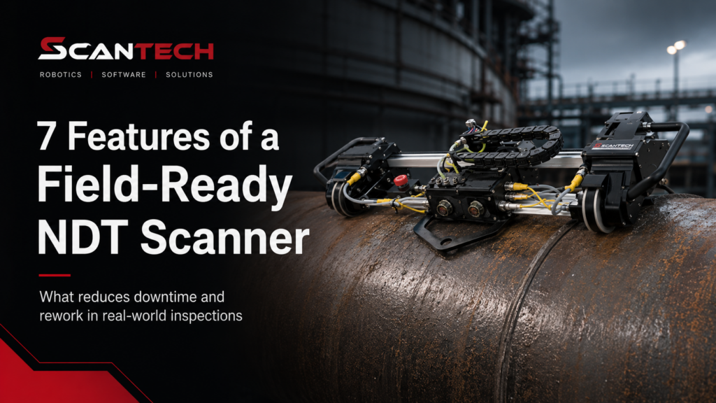
Table of Contents
7 Design Factors That Reduce Downtime and Rework
An NDT scanner can look impressive during a controlled demonstration and still be the wrong system for the field.
The real test begins when the surface is uneven, access is limited, power is nowhere nearby and the inspection has to be completed within a narrow window. Add changing pipe diameters, coatings, vertical surfaces, couplant delivery and reporting requirements, and scanner selection becomes much more than a comparison of speed and weight.
The better question is not simply, “How fast can the scanner move?”
It is, “What could cause this inspection to fail, slow down or require a second scan?”
That shift in thinking matters. A fast scanner that slips, loses contact or creates difficult-to-review data can cost more time than a slower system that works consistently from setup through reporting.
What is a field-ready NDT scanner?
A field-ready NDT scanner is an inspection system designed to maintain controlled movement, stable probe contact, reliable coupling and accurate positional data under real industrial conditions. It should also be practical to transport, configure, operate and service without creating unnecessary delays.
Field readiness is not one feature. It is the result of the complete system working together.
That includes:
Scanner movement and steering
Traction or attachment method
Probe positioning
Couplant delivery
Power and control
Software
Data review and reporting
Serviceability
This system-level view is also reflected in ISO guidance for automated ultrasonic testing, which addresses manipulation systems, controls, ultrasonic electronics, data storage, display and evaluation as connected parts of an automated UT system.
Here are seven factors that determine whether an NDT scanner is truly prepared for real inspection work.
1. Controlled motion and accurate position encoding
A robotic NDT scanner does more than carry a probe. It establishes where each measurement was taken.
That position information is critical when an inspection team needs to:
Associate thickness readings with a specific location
Build an accurate B-scan or C-scan image
Return to an area for verification
Compare current data with a previous inspection
Document the location of material loss
Generate a repeatable inspection report
Small motion errors can become larger data problems. Wheel slippage, inconsistent indexing or uncontrolled steering may cause measurements to appear in the wrong location. The UT instrument may still receive a signal, but the resulting map may not accurately represent the asset.
This is why an encoded scanner should be evaluated by more than its maximum travel speed. Buyers should ask how the system maintains positional accuracy when changing direction, moving across uneven surfaces or steering on curved assets.
The Axis inline B-scan scanner provides a useful example. Its integrated magnetic encoder tracks position independently from wheel movement, helping reduce the effect of wheel slippage on recorded data.
For raster scanning, motion between scan lines matters too. Smooth, controlled indexing reduces unnecessary stops and helps the system maintain a predictable scan pattern.
The goal is not motion for the sake of motion. It is movement that protects the relationship between the probe, the surface and the data.
2. Reliable traction and surface adaptation
A scanner cannot collect reliable data if it cannot maintain its position on the asset.
Traction becomes especially important when working on:
Vertical tank walls
Inverted surfaces
Small-diameter piping
Curved vessels
Uneven or coated surfaces
Non-ferrous materials
Areas with changing geometry
On ferrous assets, magnetic wheels can provide the attachment force needed for vertical and inverted scanning. However, magnetic strength alone does not solve every problem.
The wheels still need to maintain useful surface contact. A rigid scanner may sit securely on a flat plate but struggle when the surface radius changes. Suspension, wheel angle and the scanner’s overall geometry all affect how well it conforms to the asset.
The Axis scanner weighs approximately 10 pounds while providing pulling force greater than five times its own weight. Its wheel configuration also self-adjusts to inner and outer radii to maintain magnetic-wheel contact.
For non-ferrous materials, a different attachment method may be required. The Vertex two-axis scanner platform can operate with magnetic wheels on carbon steel or use a chain attachment on materials where magnetic adhesion is not available.
This flexibility matters because the inspection method may stay the same while the asset material changes.
Before choosing a scanner, inspection teams should confirm:
The asset material
Minimum and maximum diameter
Surface orientation
Coating condition
Expected curvature
Required scanning direction
Available clearance around the inspection area
A field-ready scanner should fit the actual asset, not an ideal version of it.
3. Stable probe contact and controlled couplant delivery
Good ultrasonic data begins at the point where the probe meets the surface.
The scanner can follow the correct path and maintain perfect encoder accuracy, but the data can still suffer if probe contact changes throughout the scan.
Common causes of inconsistent coupling include:
Surface curvature
Weld crowns
Scale or roughness
Changing probe pressure
Air bubbles in the water column
Inconsistent couplant flow
A probe holder that tilts or flips
Excessive vibration during movement
According to the ASNT overview of ultrasonic testing, ultrasonic inspection relies on transducers to introduce sound waves into the test material. In contact UT applications, reliable acoustic transfer between the probe and surface is essential.
A field-ready probe mechanism should maintain contact force without forcing the probe into the asset so aggressively that it creates drag or unnecessary wear.
For example, the Apex modular scanner platform uses a near-constant-force spring design and an anti-tip probe mechanism. These features help the probe remain stable while passing over surface changes.
Couplant delivery also deserves attention. Too little water can cause signal loss. Too much uncontrolled flow can create a mess, increase water use and introduce turbulence.
The WS3 couplant delivery system provides adjustable flow control and a battery-powered option for mobile inspections. Matching the couplant flow to the probe and application can improve acoustic consistency while reducing unnecessary water use.
When reviewing a scanner, ask to see the live signal while the unit moves across the actual inspection geometry. A clean product photo will not reveal whether probe pressure or coupling remains stable during motion.
4. Rugged construction in the areas that matter most
“Rugged” is one of the most overused words in industrial equipment marketing.
A thick outer housing may look durable, but true field reliability depends on what is protected inside the scanner.
The drive system, bearings, gears, motors, encoders and electrical connections all face real exposure to:
Water and couplant
Dirt and debris
Repeated transportation
Vibration
Magnetic particles
Temperature changes
Impacts during setup
Long inspection cycles
The cost of a mechanical failure is rarely limited to the repair itself. A failed drive section may also mean lost inspection time, additional labor, equipment rental, travel delays or a second mobilization.
That is why drive construction deserves close attention.
The XR Spider corrosion mapping scanner uses custom-engineered stainless-steel gear trains directly coupled to all four wheels. The gear components are housed in sealed enclosures to support strength and lower maintenance requirements in industrial environments.
Direct drive and sealed components reduce the number of vulnerable points where contamination, wear or mechanical play may affect performance.
Service access matters too. Components that require lengthy disassembly can turn a minor issue into hours of downtime. A field-ready system should make routine inspection, cleaning and attachment changes straightforward.
The best way to judge ruggedness is to look beyond the exterior. Ask how the drive system is built, which areas are sealed, what maintenance is required and how quickly common components can be accessed.
5. Fast setup and useful modularity
The scanner is not producing inspection data while it is sitting in a case.
Setup time often receives less attention than scan speed, but it can have a major effect on the total job timeline. This is especially true when a crew must inspect multiple pipe sizes, change scanning directions or move between B-scan, C-scan and weld inspection configurations.
Useful modularity should make a system easier to adapt without making it complicated to assemble.
Look for features such as:
Tool-free attachment changes
Quick wheel-angle adjustments
Interchangeable probe holders
Adjustable raster widths
Common control connections
Components shared across scanner platforms
Support for multiple probe types
Compatibility with existing UT instruments
The Apex universal scanner can be configured for inline B-scanning or automated C-scan corrosion mapping. Its attachment points and wheel-angle adjustments are designed for quick, tool-free changes.
The Vertex scanner platform supports front raster, side raster and multi-probe weld-scanning configurations. It can also connect with third-party phased array systems.
That last point can have a major effect on total ownership cost.
An inspection company may already have UT instruments, probes and established procedures. Replacing that entire ecosystem just to add encoded motion can create unnecessary expense and retraining.
Scanner compatibility should expand an existing inspection program, not automatically force it to start over. ScanTech discusses this approach further in its guide to phased array UT system compatibility.
Modularity is valuable when it removes limitations. It becomes a problem when the crew needs a large collection of tools, adapters and instructions just to move between routine configurations.
6. Portable power and practical scanner controls
Field portability is not just about scanner weight.
A lightweight crawler can still be difficult to deploy if it depends on several large control boxes, an excessive number of cables or a constant AC power source.
The complete field kit should be considered:
Scanner
Controller
UT instrument
Laptop or tablet
Couplant system
Batteries
Cables
Probe assemblies
Safety equipment
Spare parts
Every additional connection creates another setup step and another potential troubleshooting point.
Portable control options such as the Batt Pack NDT scanner controller can reduce dependence on stationary power and make scanner operation more practical in remote or difficult-to-access areas.
Controls should also make sense while the technician is watching the scanner. Basic functions such as steering, speed adjustment, starting, stopping and emergency response should not require the operator to look away from the equipment for long periods.
A practical field control system should offer:
Clear directional control
Predictable speed response
Accessible stop functions
Manageable cable routing
Simple connection points
Battery options suited to the expected shift
Controls that can be used while wearing work gloves
The right control setup depends on the application. A tank-wall inspection may have different requirements than a short pipe scan or a remote pipeline job. The important point is to evaluate the entire working system, not only the scanner base.
7. Software that protects the value of the inspection data
The inspection is not finished when the scanner stops moving.
Data still has to be reviewed, cleaned up when appropriate, organized, reported and delivered to the customer or asset owner.
Poor software can shift hours of work from the field into the office. It can also make valuable scan data difficult to understand or compare later.
Field-ready software should support the technician throughout the workflow:
Scanner setup
Calibration
Data acquisition
Live monitoring
Data review
Reporting
Export or long-term storage
For encoded B-scanning, Analyst X software includes guided calibration, real-time data viewing, pause-and-resume repositioning, post-scan re-gating and automated reporting. Reports can include scan plans, B-scans, overlays, charts and thickness-value tables.
For automated C-scan corrosion mapping, Analyst XR software provides real-time acquisition, post-scan re-gating, customizable reporting, 3D corrosion modeling and B31G analysis.
The difference between B-scan and C-scan is important when selecting a workflow. A B-scan displays a profile view through the material, while a C-scan presents data as a top-down map tied to surface position.
Neither format is automatically better. The right choice depends on the inspection objective, required coverage and reporting method.
Software should make the data easier to defend, not simply more attractive on a screen.
Why scan speed alone can be misleading
Maximum speed is easy to compare because it fits neatly into a specification table.
Total inspection time is more complicated.
A fast scanner may not create a faster job when the crew has to stop repeatedly to:
Correct wheel alignment
Restore probe contact
Adjust couplant flow
Reposition cables
Repeat missed areas
Reconfigure attachments
Clean up inconsistent data
Manually rebuild the final report
The fastest scan is the one that only has to be completed once.
This does not mean speed is unimportant. It means speed should be evaluated alongside stability, coupling, encoder accuracy and data-acquisition limits.
A scanner moving faster than the UT system can reliably acquire data is not improving productivity. It is simply moving faster.
Questions to ask before selecting automated NDT equipment
Before purchasing or renting a scanner, ask the manufacturer to demonstrate the complete workflow.
Motion and traction
How is scanner position encoded?
How does the system account for wheel slippage?
Can it scan vertically or inverted?
What happens when the surface radius changes?
Does the scanner work on ferrous and non-ferrous materials?
Probe performance
How is probe pressure maintained?
Can the probe pass over welds or surface transitions?
How is couplant delivered?
Can flow be adjusted for the probe and application?
What prevents the probe from tilting or losing contact?
Setup and compatibility
Which adjustments require tools?
How long does a normal configuration change take?
Which probes and UT instruments are supported?
Can the system use existing phased array or thickness-gauge equipment?
What components are shared across configurations?
Field operation
What is included in the full field kit?
What power sources are required?
How long can the system operate on battery power?
How are cables managed?
Which components can be serviced in the field?
Data and reporting
Can the technician monitor data during the scan?
Can stored data be re-gated?
Which report elements are generated automatically?
Can scan data be exported?
How are repeat inspections compared?
These questions expose the difference between a scanner that performs well in a demonstration and one that supports a complete inspection program.
How ScanTech approaches field-ready NDT scanner design
ScanTech develops robotic NDT scanner systems around the conditions inspection teams face outside the laboratory.
That approach includes:
Direct-drive scanner platforms
Sealed gear-train components
High-traction wheel systems
Stable probe-positioning mechanisms
Controlled couplant delivery
Tool-free modular attachments
Portable control options
B-scan and C-scan software workflows
Compatibility with third-party inspection equipment
Different inspections require different tools. A lightweight inline B-scanner may be the right choice for small-radius piping, while a steerable raster scanner may be better suited for automated corrosion mapping. Tank walls, vessels, welds and non-ferrous piping each bring their own challenges.
The objective is not to force every job into one configuration. It is to select a system that fits the geometry, method, environment and data requirements of the inspection.
Final takeaway
A field-ready NDT scanner is not defined by a single specification.
It is defined by what happens when the conditions are less than perfect.
Can the scanner maintain traction? Does the probe stay coupled? Is position recorded accurately? Can the crew change configurations without losing hours? Will the software turn the scan into a usable report?
Those are the details that determine whether automated NDT equipment reduces downtime or creates another source of it.
The right system should make the inspection more controlled, more repeatable and easier to complete from setup through final reporting.
Explore field-ready NDT scanner solutions
ScanTech manufactures automated ultrasonic scanner systems for corrosion mapping, inline B-scanning, weld inspection, pipe inspection and other industrial NDT applications.
Explore ScanTech’s complete line of NDT ultrasonic scanners, review available tank inspection solutions or book an NDT scanner demonstration to discuss the application with the ScanTech team.
Frequently Asked Questions
What makes an NDT scanner field-ready?
A field-ready NDT scanner can maintain controlled movement, reliable traction, stable probe contact and accurate position data under real industrial conditions. It should also be practical to transport, configure, power, operate and service in the field.
Why is encoder accuracy important in automated ultrasonic testing?
Encoder data connects each ultrasonic measurement to a physical location on the asset. Accurate encoding supports reliable B-scan and C-scan images, repeat inspections, defect location, corrosion monitoring and inspection reporting.
Does a faster NDT scanner always reduce inspection time?
No. Maximum travel speed does not account for setup, indexing, coupling loss, re-scanning, configuration changes or reporting. A stable scanner that collects complete data in one pass may finish the overall job faster than a higher-speed system that requires repeated adjustments.
Which scanner features improve ultrasonic data quality?
Important features include stable probe pressure, controlled couplant delivery, accurate position encoding, reliable traction, low-vibration movement and software that allows real-time monitoring and post-scan review.
Can one NDT scanner support multiple inspection applications?
Some modular scanner platforms can support multiple attachments or inspection methods. Compatibility depends on the scanner, probe configuration, control system, UT instrument and software being used.
What commonly causes an automated UT scan to be repeated?
Common causes include wheel slippage, inconsistent coupling, loss of probe contact, incorrect scan setup, missed coverage, cable interference and poor data quality that is not identified until after the inspection.
Frequently Asked Questions
A field-ready NDT scanner can maintain controlled movement, reliable traction, stable probe contact and accurate position data under real industrial conditions. It should also be practical to transport, configure, power, operate and service in the field.
Encoder data connects each ultrasonic measurement to a physical location on the asset. Accurate encoding supports reliable B-scan and C-scan images, repeat inspections, defect location, corrosion monitoring and inspection reporting.
No. Maximum travel speed does not account for setup, indexing, coupling loss, re-scanning, configuration changes or reporting. A stable scanner that collects complete data in one pass may finish the overall job faster than a higher-speed system that requires repeated adjustments.
Important features include stable probe pressure, controlled couplant delivery, accurate position encoding, reliable traction, low-vibration movement and software that allows real-time monitoring and post-scan review.
Some modular scanner platforms can support multiple attachments or inspection methods. Compatibility depends on the scanner, probe configuration, control system, UT instrument and software being used.
Common causes include wheel slippage, inconsistent coupling, loss of probe contact, incorrect scan setup, missed coverage, cable interference and poor data quality that is not identified until after the inspection.