Table of Contents
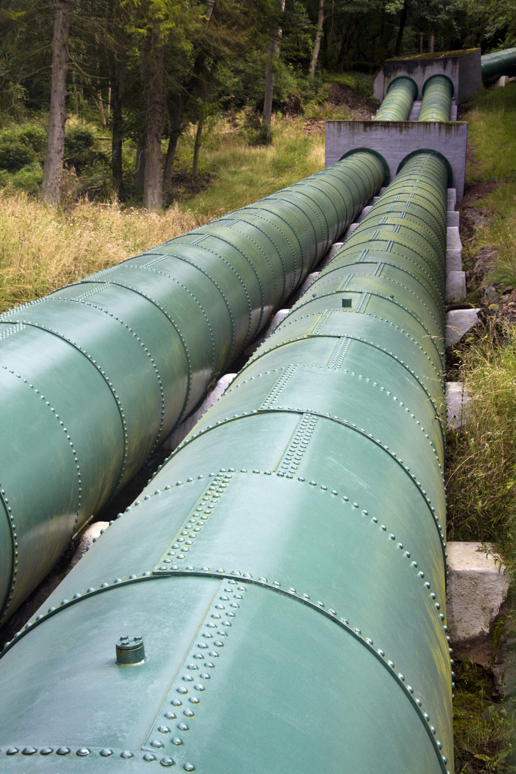
When you perform ultrasonic testing (UT) on components that have coatings, paint, corrosion scale or rough surfaces, you face additional acoustic challenges. While your baseline understanding from Ultrasonic Testing Basics gives you the core principle of sound propagation and echo return, inspection through coatings demands extra attention.
Coatings create acoustic-impedance mismatches, add extra path length, and may trap air or voids at the interface. Rough surfaces scatter the beam, reduce echo amplitude and lower signal-to-noise ratio (SNR). Because UT relies on a predictable interface for accurate time-of-flight or pulse-echo measurement, any disruption in that interface (coating variation, corrosion scale, surface roughness, coupling inconsistencies) introduces uncertainty in flaw detection, thickness measurement, or sizing.
This article walks you through the core issues, available techniques, how signal distortion occurs, mitigation strategies, and real-world examples you’ll use in your inspection practice.
Couplant & Interface Issues
Interface & Couplant Challenges
One of the primary field obstacles is achieving consistent acoustic coupling when surfaces are coated or rough. UT transducers require a coupling medium (gel, oil, water, delay-line) between probe and surface. When coatings or roughness intervene:
- Air gaps between coating and substrate severely reduce energy transmission.
- Uneven surfaces cause variable path lengths, beam scattering, and inconsistent delay times.
- Thick or highly attenuating coatings add to the probe’s dead zone and may absorb or scatter sound energy before reaching the substrate.
Selecting the correct couplant and configuring the interface technique becomes critical. For example, research shows that surfaces with higher roughness yield lower crack-echo amplitudes; therefore, the interface condition must be documented and considered when interpreting results. As an NDT technician, you must assess: the coating thickness and type, substrate condition, surface roughness, coupling medium choice, whether localized surface removal is feasible, and whether a delay-line or immersion technique might be required.
Techniques (Delay Lines, Immersion)
Alternative Methods When Contact Coupling Fails
When surface conditions make direct contact coupling unreliable—due to thick coatings, heavy roughness, high temperature or contamination—you’ll need to consider alternative UT techniques:
- Delay-line probes: A solid wedge (delay block) is used between the probe and surface to shift the “dead zone” and isolate the substrate measurement from coating/interface noise.
- Immersion technique: The component or probe is submerged in water (or coupling fluid) enabling uniform coupling and eliminating air gaps, particularly useful when surfaces are rough or coated.
- Dual-element probes: Separate transmit and receive elements (often angled) help bypass near-surface dead zones and reduce interface noise from coatings/roughness. For example, OnestopNDT notes dual-element probes are effective for thick coatings. When choosing your technique, weigh: coating thickness, substrate accessibility, defect depth (near surface vs deeper), acceptable dead-zone, temperature, and inspection environment.
Signal Distortion
How Coatings & Rough Surfaces Alter UT Signals
Surface condition doesn’t just affect coupling—it actively distorts the ultrasonic signal in multiple ways:
- Amplitude reduction: Rough surfaces scatter the beam and attenuate the signal, reducing SNR. Studies indicate that elevated surface roughness (Ra) values significantly degrade echo amplitude.
- Beam misdirection: Uneven surfaces or steps cause the beam to deviate or tilt, effectively changing the propagation path and arrival time—resulting in measurement error or mis-location of flaws.
- Dead-zone enlargement: Thick coatings or wedge/adapter setups push the near-surface measurement zone further away, limiting your ability to detect shallow defects.
- Interface noise or multiple echoes: Coating–substrate boundaries or trapped air bubbles generate extra echoes that may mask legitimate flaw echoes or confuse sizing interpretation. As the technician, calibrate your setup using similar surface conditions, check echo amplitude consistency, and document repeatability. If echo amplitude drops or noise increases, the surface condition is likely reducing reliability.
Mitigation Methods
Best Practices for UT on Coated or Rough Surfaces
To overcome the challenges of coatings and rough surfaces, apply these mitigation methods:
- Surface preparation: Remove or locally clean coatings/corrosion scale, grind flat key areas, remove trapped debris, ensure surface is flat and free of major steps or spikes. ASME or other standards underline the importance of controlling surface steps for reliable UT.
- Proper probe selection: For thick coatings or near-surface defects, use dual-element or delay-line probes. For thinner coatings and standard substrate, high-frequency direct-contact may suffice.
- Appropriate frequency choice: Lower frequencies (1–5 MHz) improve penetration through coatings or rough surfaces but offer less resolution; higher frequencies (10+ MHz) give better resolution but are more sensitive to attenuation.
- Optimized coupling: Use high-viscosity gels for rough/vertical surfaces, purge air pockets, consider immersion when coupling is very challenging.
- Calibration under realistic conditions: Use reference or calibration blocks that mimic the coated/rough condition you’re dealing with. This ensures your baseline is relevant to the actual substrate scenario.
- Signal processing & gating: Adjust gain, time-base, apply filters, gate out interface echoes, compare to baseline amplitude, and repeat measurements to confirm consistency. Link this with your broader corrosion monitoring workflow (see Corrosion Monitoring via Ultrasonic Thickness Gauging).
- Document everything: Log surface condition, coupling method, echo levels, attenuation, and any mitigation steps. If conditions are outside acceptable limits, consider alternative techniques (immersion UT, TOFD, phased-array) or flag for further review. By systematically applying these methods, you raise your inspection reliability and reduce the risk of missed defects or inaccurate readings.
Examples
Example 1: Coated Steel Pipe Inspection
In a mid-stream pipeline inspection campaign, operators encountered steel pipes coated with epoxy and insulation. UT technicians used a delay-line probe and low-frequency transducer configured on a coated mock-up to calibrate coupling and verify amplitude behaviour through the coating. Despite the coating layer, they detected wall thinning of ~0.8 mm compared to baseline. Key success factors: adequate probe selection, coupling strategy, and documentation of coating thickness.
Example 2: Rough Storage Tank Shell Interior
A storage tank shell interior exhibited heavy corrosion and rough substrate surface (Ra ~20 µm). Prior to UT, technicians mechanically cleaned scale, applied gel couplant, and in areas where roughness remained, switched to an immersion setup. The improved surface condition and coupling led to repeatable echo amplitudes and reliable thickness readings—demonstrating how preparation and technique overcome rough surface challenges.
Example 3: Painted Composite Structure in Aerospace
In an aerospace inspection of a painted aluminum skin, initial UT readings were inconsistent: low echo amplitude and fluctuating results. The team applied a thin delay-layer, purged paint beneath the probe, selected appropriate gel, and adjusted gain/time-base to compensate for the paint layer. This aligns with research showing coated surfaces reduce SNR unless mitigated.
Takeaway: Even thin coatings or rough finishes need accurate coupling and calibration to ensure reliable UT results.
What to Do Next
Develop Your Inspection Plan for Coated or Rough Surfaces
With the fundamentals understood, your next step is to integrate these strategies into your inspection program:
- Identify locations with coatings, paint, corrosion scale or rough surfaces and flag them in your inspection schedule.
- Choose appropriate probes, couplant types, calibration blocks or mock-ups for your actual surface conditions.
- Define signal acceptance criteria, amplitude thresholds, and dead-zone limits specific to coated/rough conditions.
- Document surface preparation, coupling conditions, echo behaviour, and verify repeatability.
- Train your inspection team on handling coated or rough surfaces, and decide in advance when alternative methods (immersion, TOFD, phased-array) may be needed. If you’d like help building or reviewing your UT inspection plan for coated or rough surfaces—or linking this into your broader corrosion monitoring framework (see Corrosion Monitoring via Ultrasonic Thickness Gauging).


