What is corrosion mapping in ultrasonic testing? Ultrasonic corrosion mapping is a grid-based ultrasonic testing (UT) method that measures remaining wall thickness across an area and converts those readings into a C-scan thickness map. Instead of collecting a single thickness value or a line profile, corrosion mapping captures many thickness points over a defined surface so metal loss patterns are visible, documentable, and repeatable.
For a practical overview of where this method fits across industrial inspection programs, see corrosion mapping solutions.
Clear definition
Ultrasonic corrosion mapping: A structured UT process that measures thickness across a surface using a defined grid (or raster) and produces a C-scan map showing thickness variation and metal loss patterns.
This definition matters because “corrosion mapping” is sometimes used loosely to describe any thickness work. In practice, corrosion mapping implies two things:
- Area coverage (not a single spot or a single line)
- Map output (a C-scan visualization tied to position)
Why corrosion mapping exists
Corrosion rarely removes thickness evenly. It creates patterns: pitting clusters, bands of erosion, localized under-deposit corrosion, edge thinning, and transition zones near welds or flow disturbances.
A single thickness reading can miss those patterns. Even a handful of readings can miss the worst area if spacing is too wide or sampling is inconsistent.
Corrosion mapping answers a different question:
- Not “What’s the thickness right here?”
- But “What does thickness look like across this whole area?”
That’s why mapping is used when teams need to see wall loss clearly enough to plan repairs, define follow-up inspection scope, or establish a baseline for future comparison.
Grid-based scanning explained
Grid-based scanning is what makes corrosion mapping repeatable.
The grid
A grid is a defined layout of measurement points (or a defined raster path) across a surface area. A solid grid definition includes:
- Scan boundary (length × width)
- Point spacing (grid increment)
- Origin point (where “0,0” starts)
- Orientation (direction of scan so it can be repeated later)
Resolution and spacing
Grid spacing drives the detail level:
- Tighter spacing captures smaller features (more time, more data)
- Wider spacing covers faster (less detail)
The goal isn’t maximum data. The goal is enough resolution to capture the corrosion pattern that matters for the inspection objective.
Raster scanning
Raster scanning is a back-and-forth path that covers a defined width over a defined length. It’s commonly used because:
- coverage is systematic
- results are easier to validate
- maps are easier to interpret and compare later
How ultrasonic corrosion mapping is performed
This is the typical workflow regardless of platform, as long as the output is a mapped C-scan.
Step 1: Define the objective and scan area
- Identify the asset and risk zone
- Define what the map needs to answer (baseline, follow-up, repair planning, screening)
- Mark the scan boundary on the surface (or define it in the plan)
Step 2: Set grid increments and positioning rules
- Choose point spacing (resolution)
- Define the origin and orientation
- Confirm scan direction and any required overlap rules
Step 3: Prepare the surface for stable coupling
Surface condition affects data quality.
- Remove debris or loose scale that disrupts coupling
- Confirm the couplant strategy used for conventional UT workflows
Step 4: Acquire thickness data across the grid
- Maintain stable probe contact
- Maintain consistent travel and coverage
- Watch for dropouts and follow procedure for re-scan rules
Step 5: Validate coverage before leaving the area
A good map is complete and defensible.
- Confirm full area coverage
- Confirm no gaps from coupling loss
- Confirm minimum thickness zones are repeatable
Step 6: Generate the C-scan thickness map
Once the data is captured and validated, the readings are converted into a thickness map for review and reporting.
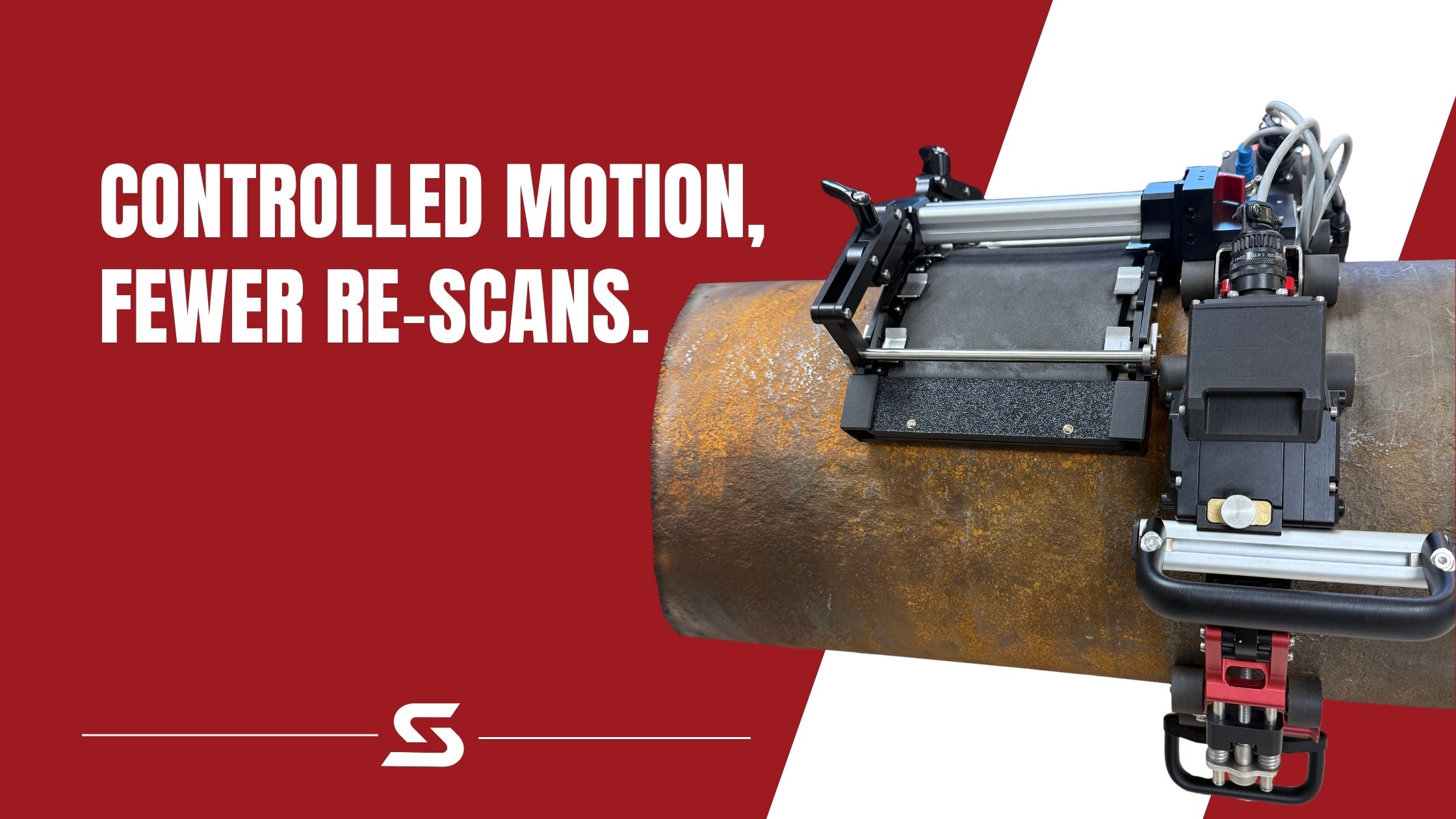
For corrosion mapping workflows designed around stable, repeatable scanning and mapped outputs, the XR Spider corrosion mapping scanner is a purpose-built platform optimized for this style of inspection.
Data outputs (C-scan maps)
Corrosion mapping is defined by its outputs. The main deliverable is a map that ties thickness values to position across the scan area.
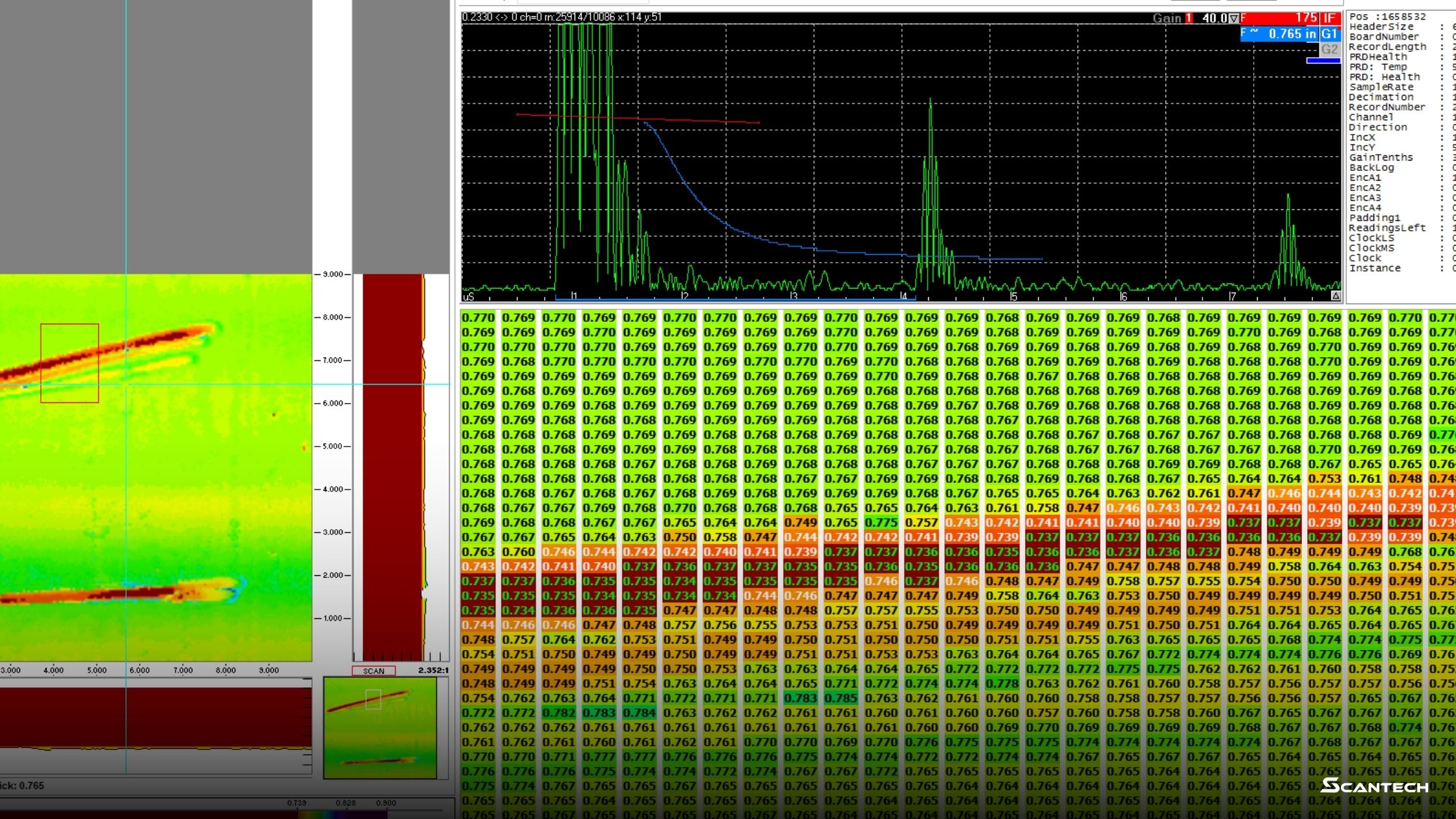
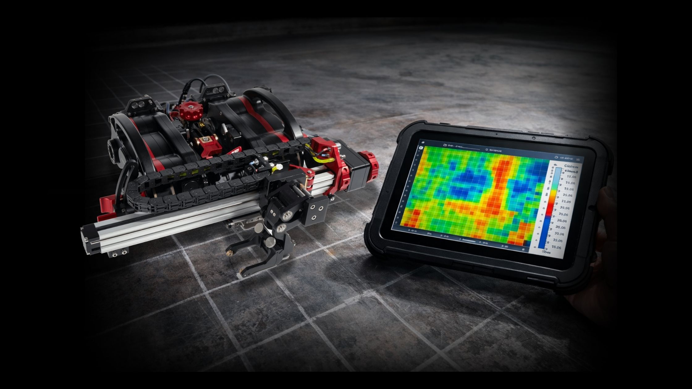
C-scan thickness map
A C-scan thickness map is a plan-view image of thickness values across the scanned area. It typically includes:
- a color scale tied to thickness range
- coordinates or grid references
- highlighted minimum thickness areas
- optional zone segmentation (plates, bands, target regions)
Minimum thickness and location
A useful map should make it straightforward to answer:
- What is the minimum thickness?
- Where is it located (grid position or coordinates)?
- Is it isolated pitting or broader thinning?
Supporting tables and summaries
Depending on reporting requirements, outputs may also include:
- thickness distribution summaries
- averages and variability measures
- exportable tables for recordkeeping and review
Common mistakes and how to avoid them
Grid is too coarse
If spacing is too wide, small pitting clusters can be missed or “averaged out.” The map looks clean but doesn’t reflect risk.
Coverage isn’t validated
A map can look complete while hiding coupling dropouts. Coverage checks prevent “pretty but incomplete” outputs.
Confusing C-scan mapping with B-scan profiling
Corrosion mapping (C-scan) is area-based visualization. B-scan is a line-based profile used for thickness profiling and documentation workflows. Mixing terms creates scope confusion.
Surface readiness varies across the scan area
Mapping becomes unreliable when coupling conditions change significantly across the area. Surface condition and coupling consistency matter.
Glossary: Ultrasonic Corrosion Mapping Terms
Corrosion mapping (UT)
Grid-based ultrasonic thickness measurement across an area that produces a C-scan thickness map showing thickness variation and metal-loss patterns.
C-scan
A plan-view map that displays thickness values across an area. In corrosion mapping, it’s typically color-coded to make thinning zones obvious.
Grid
A defined layout of measurement points over a surface area, including boundaries, point spacing, and a reference origin for repeatability.
Raster scan
A back-and-forth scan path used to cover a defined width and length. Raster paths are common for corrosion mapping because coverage is systematic and easier to validate.
Resolution (grid spacing)
The distance between measurement points. Smaller spacing increases detail but adds scan time and data volume.
Encoder
A device that tracks scanner movement so thickness readings can be tied to position. Encoders support repeatable coverage and cleaner map outputs.
Couplant
The medium used to transmit ultrasonic energy between the probe and the surface in conventional UT workflows. Water is commonly used in corrosion mapping systems.
Data dropout
Missing or unreliable readings, often caused by poor coupling, surface condition, or inconsistent contact during scanning.
Minimum thickness (T-min)
The lowest measured thickness within the scan area, typically reported with a location reference so the area can be verified or re-scanned.
Repeatability
The ability to re-scan the same area later using the same grid and obtain consistent results that can be compared over time.
Next steps (where corrosion mapping fits in pipe programs)
Corrosion mapping is commonly used to support piping integrity programs where wall loss needs to be visualized, documented, and compared over time across defined zones.
For pipe workflows that pair well with corrosion mapping planning and execution, see pipe inspection solutions.
Key takeaway
Ultrasonic corrosion mapping is grid-based UT thickness measurement that produces C-scan thickness maps to reveal corrosion patterns and wall loss across an area.
Ready to discuss the inspection workflow? Book a demo using the form on this page to review requirements and best-fit configuration. Need pricing, procurement help, or a quick routing question? Contact ScanTech to get connected with the right team.