Table of Contents
Ultrasonic testing (UT) has advanced far beyond simple flaw detection. Today’s advanced ultrasonic testing methods—including Time of Flight Diffraction (TOFD), Guided Wave Testing, and Hybrid UT—offer deeper insight, higher accuracy, and safer inspection workflows for critical components.
If you’ve already explored Ultrasonic Testing Basics or Single vs Dual vs Phased Array Probes, this article will show how advanced UT tools push inspection reliability to a new level.
These methods are now standard in industries like oil & gas, aerospace, energy, and manufacturing—where detecting cracks, corrosion, or weld flaws before failure is mission-critical.
Time of Flight Diffraction (TOFD)
How TOFD Works
TOFD uses two probes positioned on opposite sides of a weld. One transmits sound; the other receives diffracted waves bouncing off flaw tips. Instead of relying only on reflected echoes, TOFD measures time of flight, producing an accurate image of flaw depth and shape.
This diffraction-based approach minimizes operator dependence and provides highly reproducible results.
Advantages of TOFD
- Excellent sizing accuracy (±0.5 mm)
- Fast data capture for large welds
- Digital, auditable inspection records
- Minimal setup and radiation-free
When to Use TOFD
TOFD is ideal when you need precise flaw sizing, volumetric weld inspection, or want a digital record for long-term monitoring. It’s widely recognized under ASME Section V and ISO 10863 as an approved method for code-compliant weld testing.
Guided Wave Testing
What Guided Waves Are
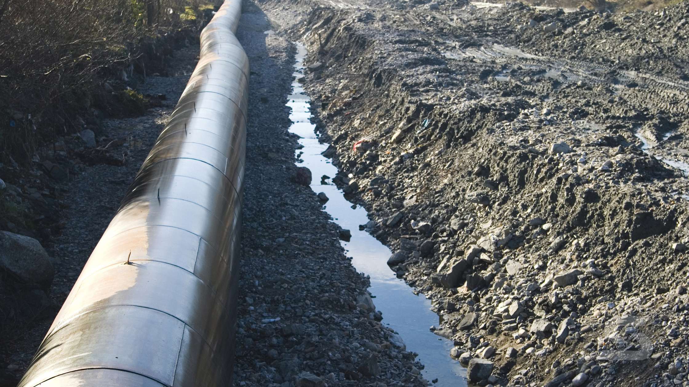
Guided waves are low-frequency ultrasonic waves (20–100 kHz) that travel along the length of structures like pipelines or tubes. Instead of inspecting locally, Guided Wave UT examines tens of meters from one access point—detecting corrosion, cracks, or weld deterioration without extensive scaffolding or insulation removal.
Advantages
- Long-range coverage (30–50 m typical)
- Non-intrusive—no need for full insulation removal
- Safe alternative to radiography
- Ideal for screening inaccessible sections
Limitations
- Less sensitive to small or shallow defects
- Needs follow-up with localized UT or PAUT
- Requires skilled calibration and signal interpretation
Guided Wave UT is best used as a screening tool—detecting suspect areas for further investigation using Phased Array UT or TOFD.
Hybrid & Multi-Mode Ultrasonic Methods
Why Combine Techniques?
Combining multiple ultrasonic techniques—such as PAUT + TOFD or UT + Eddy Current—increases reliability and coverage.
- PAUT provides a high-resolution, multi-angle view of internal defects.
- TOFD measures depth with high accuracy.
- Eddy Current or SH-Wave modes add sensitivity to surface-breaking or bond-line flaws.
This hybrid approach gives technicians the best of both worlds: detailed imaging plus precise flaw sizing.
Visual Idea 3 (Hybrid Setup)
A split view showing TOFD grayscale imaging paired with PAUT sector scans for full weld coverage.
Benefits
- Near 100% volumetric weld coverage
- Real-time imaging with precise sizing
- Digital data for audit trails and reporting
- Reduced radiation and field-time vs RT
Use Cases
- Pipeline weld verification
- Pressure vessel seam inspection
- Bonded composite structure evaluation
- High-value component quality assurance
Applications and Advantages
| Industry | Method | Advantages |
| Oil & Gas | Guided Wave + TOFD | Long-distance corrosion detection and weld sizing |
| Power Generation | TOFD + PAUT | Creep crack and fatigue monitoring |
| Aerospace | Hybrid UT + Eddy Current | Detects delamination and disbonding |
| Manufacturing | TOFD | Rapid, accurate weld flaw sizing |
| Infrastructure | Guided Waves | Screen pipelines, risers, and support legs |
Limitations to Consider
Even advanced ultrasonic testing methods have some constraints:
- TOFD has difficulty detecting surface-breaking cracks near probe zones.
- Guided waves are less precise for small flaws or complex geometries.
- Hybrid systems require skilled operators and increased data processing.
Still, when combined strategically, these methods deliver unmatched data quality and coverage for most inspection challenges.
When to Use Each Advanced UT Method
| Inspection Type | Best Technique | Why Use It |
| Weld defect sizing | TOFD or PAUT + TOFD | Accurate depth sizing |
| Long-range corrosion mapping | Guided Wave | Covers long distances |
| Composite & bonded structure | Hybrid UT | Detects disbonds/delamination |
| General pipe integrity | Guided Wave + Local PAUT | Fast screening and detail confirmation |
Final Takeaway: Modern UT for Modern Materials
As infrastructure ages and composite usage grows, advanced ultrasonic testing methods are now essential. They reduce downtime, improve accuracy, and eliminate radiation risks associated with older inspection methods.If you’re building a modern NDT business, begin with Ultrasonic Testing Basics and progress into Phased Array in Weld Inspection. For large-scale or specialized assets, TOFD, Guided Waves, and hybrid setups will give you the insight today’s industries demand.

