Digital Radiography in NDT: Pros, Cons & Use Cases
HomeNewsDigital Radiography in NDT: Pros, Cons & Use Cases
Table of Contents
Digital Radiography Overview
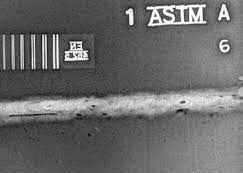
Digital radiography (DR) is an evolution of conventional radiographic testing that uses digital detectors—such as flat panel detectors or computed imaging plates—to directly capture x-ray images and convert them into electronic data (instead of using film).
Because DR does not require chemical development, images are available almost instantly, can be enhanced digitally, and are easier to store, share, and analyze.
In the world of weld inspection and industrial NDT, ISO 17636-2 defines practices and quality criteria for digital radiographic testing of fusion-welded joints. Meanwhile, ISO 17636-1 defines film-based radiographic techniques, which still matter as a comparative baseline.
Digital radiography can be subdivided into:
Computed Radiography (CR) — using imaging plates (photostimulable phosphor plates) that are scanned to digitize the image
Digital Radiography (DDR / DR with digital detectors) — uses flat or flexible panel detectors that convert x-ray photons directly into electronic signals
How DR Works (Technical Flow)
X-ray / Gamma Source A radiation source emits x-rays or gamma rays at controlled energy levels.
Detector / Imaging Device
In CR, an imaging plate captures the exposure; then it’s scanned by a reader to convert latent image to digital.
In DR, a flat panel detector (often with scintillator + photodiode array) captures and converts x-ray attenuation to an electronic image.
Signal Processing The raw digital image is processed by software (contrast/brightness adjustment, filtering, enhancement) to improve defect visibility.
Display & Analysis The image is displayed on a workstation; operators can zoom, pan, annotate, compare with standards, and archive.
Archiving & Sharing Digital images can be stored, backed up, transmitted, or compared across sites with ease.
Because DR removes the need for film handling and darkrooms, the workflow is faster and safer, especially in field use.
Advantages of DR vs Film Radiography
Advantage
Explanation
Supporting Source
Speed / Instant Imaging
DR provides immediate image preview—no waiting for film development.
OnestopNDT, Inspectioneering
Lower Radiation Dose
DR often requires less exposure to produce comparable image quality.
NDT blog, Vidisco
No Chemicals / Film Handling
Eliminates chemical processing, reducing consumables and environmental hazards.
Inspectioneering
Better Dynamic Range & Contrast
Digital detectors capture a broader range of brightness levels, making it easier to see both low and high attenuation areas.
OnestopNDT
Image Enhancement & Post-processing
Operators can zoom, adjust contrast, apply filters, overlay standards, etc.
NDT blog, OnestopNDT
Efficient Storage & Sharing
Digital images are easier to store, backup, and transmit, eliminating film archiving challenges.
OnestopNDT
Operational Efficiency & Field Use
DR systems are increasingly portable, enabling inspections in remote or confined settings.
NDT.net, OnestopNDT
One case: moving from film to computed radiography in piping functions has cut inspection time by ~50 % and reduced lifecycle costs by about 25 %.
However, DR systems typically have a higher upfront cost (detectors, software, hardware) compared to film-based systems.
Challenges / Limitations & Considerations
While DR offers many benefits, it comes with trade-offs and constraints:
Detector Cost & Durability Flat panel detectors are expensive and sensitive. Dropping or mishandling them can damage panels.
Spatial Resolution vs Film In some applications, film can offer higher resolution or sharper grain under certain conditions.
Dynamic Range Saturation / Overexposure If exposure is too high, digital detectors may saturate and lose contrast detail.
Detector Size & Geometry Limitations Detectors may not conform to tight or curved geometries (though CR plates are more flexible).
Software & Calibration Needs Proper calibration, correction algorithms, and software versioning are critical. Standards like ISO 17636-2 lay out guidance.
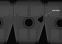
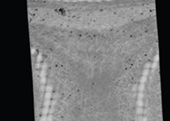
Image Artifacts & Noise Digital noise, scatter, beam hardening artifacts, and stitching artifacts can degrade interpretability if not managed.
Radiation Safety & Regulation Even though DR may reduce total dose, radiation hazards remain. Regulatory compliance (shielding, licensing, safety zones) is mandatory.
Legacy & Standards Mismatch Older inspection programs or specifications may mandate film or reference prior film-based baselines, complicating adoption.
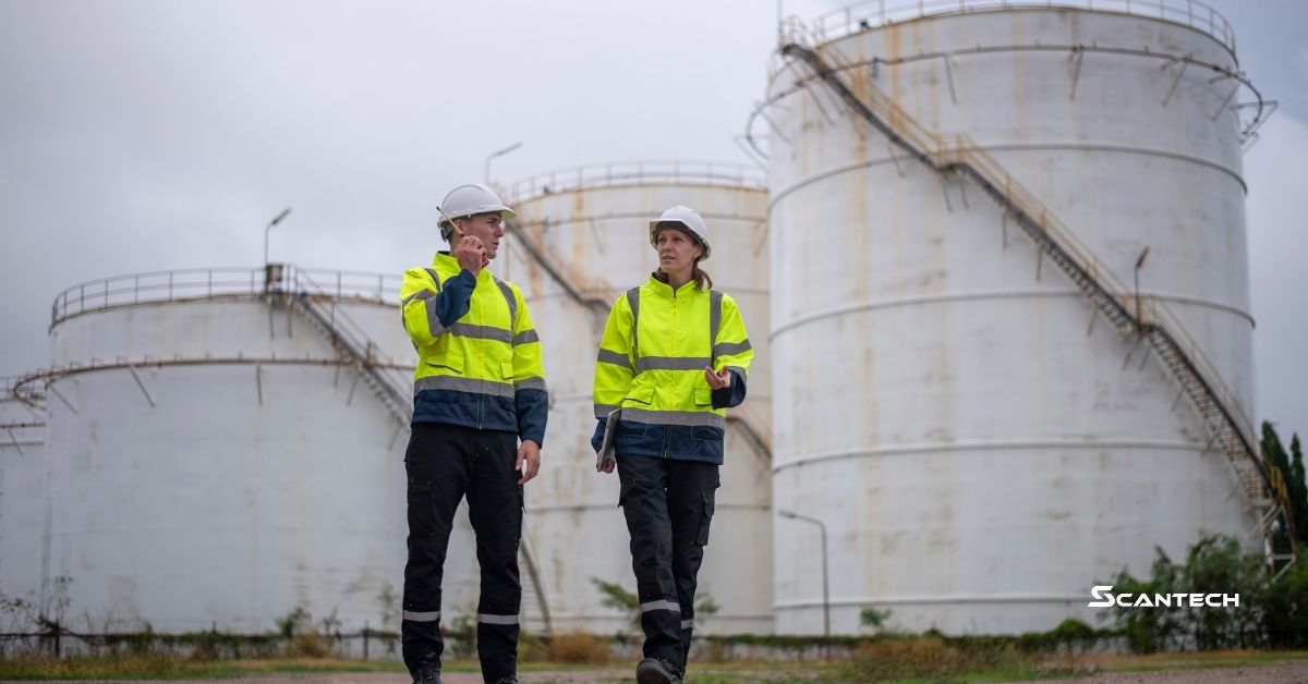
Industrial Use Cases & Applications
DR is increasingly adopted across sectors where defect detection, speed, and data management matter.
The decision between digital radiography and ultrasonic testing depends on many factors. Here’s a comparative look:
Scenario / Requirement
Favor DR
Favor UT
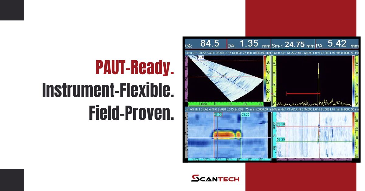
Need full volumetric imaging of weld internals
✅ DR
Simple thickness or corrosion mapping
✅ UT
Complex geometry or limited line-of-sight
✅ UT (especially phased array)
Access constraints (field, confined)
✅ portable DR if safe
✅ UT often easier
Radiation safety constraints
✅ UT (no ionizing radiation)
Data storage, sharing & traceability
✅ DR (digital)
UT may require data transfer systems
Cost consideration (capital vs consumables)
May be higher initial cost
Lower initial cost, but may need probes, calibration
Defect types (surface vs internal)
✅ DR good for internal & volumetric
✅ UT strong for subsurface, cracks, interfaces
Find the Right Tool for Each Job
Digital radiography has transformed how we do volumetric inspections in NDT: faster results, richer image data, and easier data handling. But it’s not a universal solution—understanding its limits (cost, calibration, detector constraints) helps you choose the right tool for each job.
If you’re comparing UT vs DR for a specific use case (e.g. welds, pipeline, composites), drop me the details and I’ll help you pick and design the inspection method.
Common Questions (FAQ)
Is DR replacing film in NDT?
In many sectors, yes — DR is gradually overtaking film because of workflow speed, flexibility, and image management. But film still has niches where its resolution or conformability matters.
What resolution can DR achieve?
Modern digital detectors can achieve pixel sizes down to tens of microns (depending on detector specs). The effective resolution, however, depends on detector type, geometry, exposure, and signal processing.
What industries use DR?
DR is used in oil & gas, aerospace, manufacturing, power generation, research, and anywhere volumetric inspection or fast imaging is beneficial.