Table of Contents
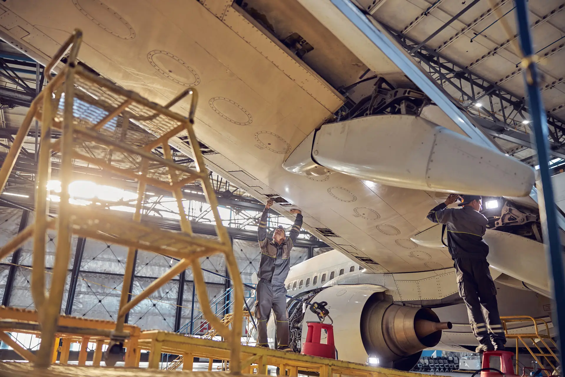
UT in Aerospace
In aerospace manufacturing and maintenance, ultrasonic testing (UT) plays a critical role in ensuring component reliability, safety, and longevity. From aircraft wings to turbine blades, UT helps identify internal flaws that could compromise structural integrity.
Unlike traditional welding applications, aerospace inspections often involve thin sections, complex curves, composite materials, and stringent regulatory standards. Every scan, echo, and indication must be interpreted with precision — because failure in flight is never an option.
If you’re new to UT or need a refresher, review Ultrasonic Testing Basics and Single vs Dual vs Phased Array Probes for background on wave behavior, transducer design, and signal interpretation.
Materials & Geometries in Aerospace
The aerospace industry uses a wide variety of materials — from lightweight composites to high-strength titanium alloys — each presenting unique ultrasonic inspection challenges.
Common materials include:
- Aluminum alloys: Easy to inspect with longitudinal or shear waves but susceptible to grain noise at high frequencies.
- Titanium: Offers excellent strength-to-weight ratio but higher acoustic attenuation, requiring lower frequencies or immersion setups.
- Carbon fiber composites (CFRP): Anisotropic structure scatters sound, so signal interpretation requires experience.
- Honeycomb panels: Multiple bonded layers create air gaps that cause false indications if not calibrated correctly.
Geometrical challenges:
Aircraft components rarely have flat, uniform surfaces. Wings, fuselage skins, and turbine housings all introduce curvature and thickness variation. Techniques like phased array UT and immersion testing help adapt to these contours by electronically steering or focusing the beam.
Typical Defects Detected by UT
Aerospace structures face fatigue, manufacturing, and service-induced flaws. Ultrasonic testing detects many of these before they become critical.
Common defect types include:
- Delamination: Separation between composite layers; shows up as a loss of backwall echo or diffuse reflections.
- Inclusions: Entrapped foreign material or resin pockets in composites.
- Disbonds: Separation between adhesive layers or honeycomb cores and skins.
- Corrosion thinning: Detected in aluminum structures and fuel tanks.
- Cracks or fatigue damage: Often found in fastener holes or high-stress regions.
Interpreting delamination signals:
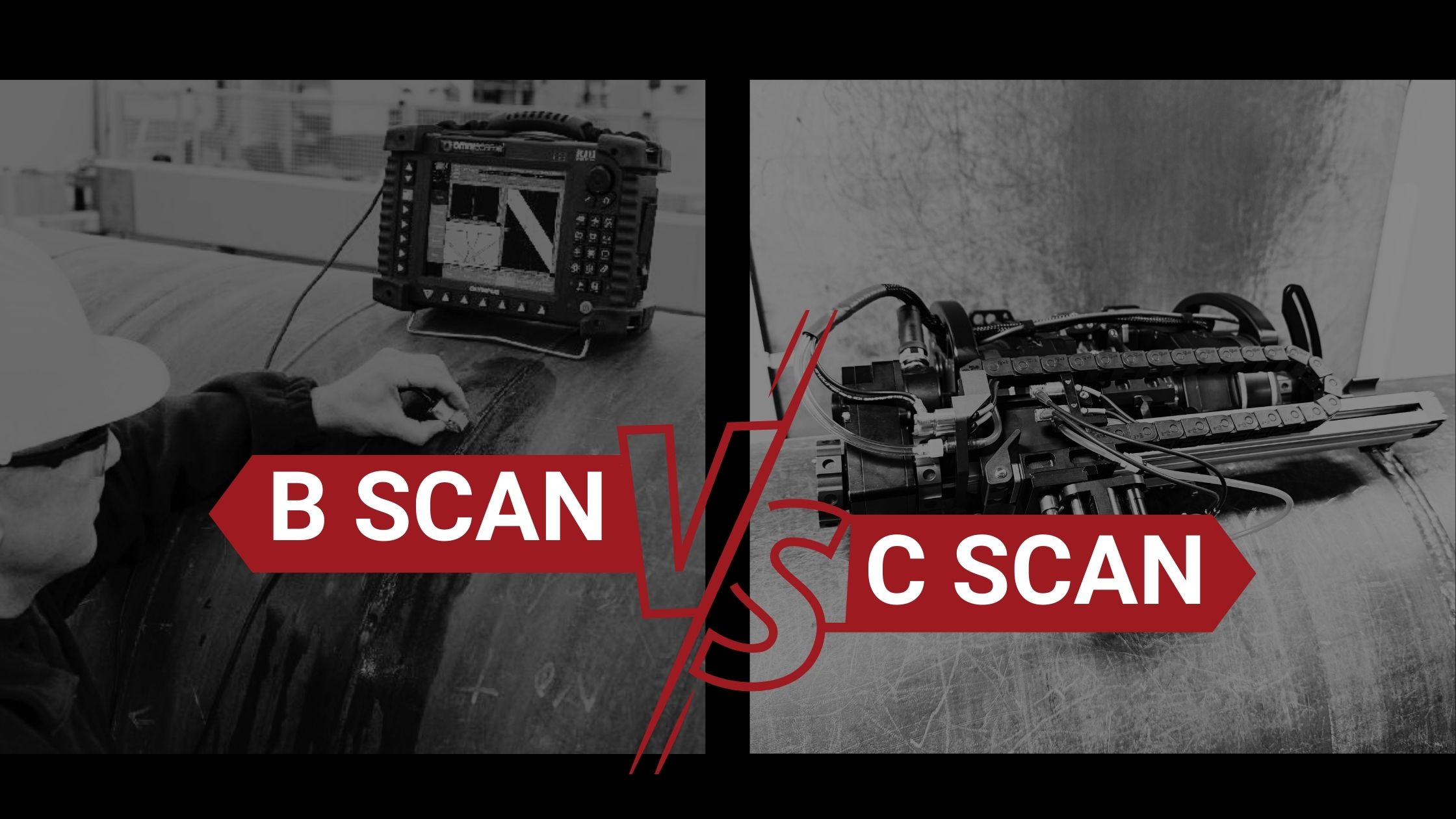
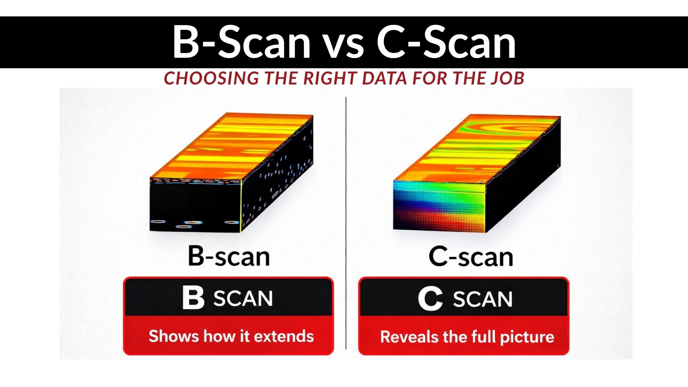
A delamination typically appears as a broad, weak reflection occurring before the backwall echo. The signal may vary with probe angle or pressure. Using through-transmission or phased array C-scan imaging helps confirm delamination size and shape.
Special Probes & Couplants
The unique geometry and materials of aerospace parts require specialized transducers and couplants.
Probe Types:
- Delay line probes: Ideal for thin materials; improve near-surface resolution.
- Immersion probes: Provide uniform coupling and precise scanning for curved surfaces.
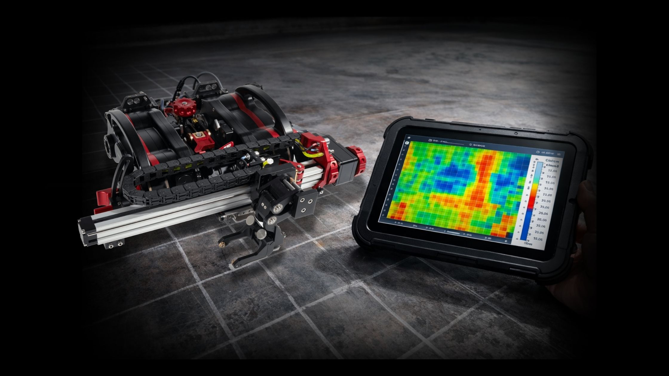
- Phased array probes: Allow electronic focusing, multi-angle inspection, and C-scan mapping.
- High-frequency probes (5–20 MHz): Used for fine defect resolution in thin skins or adhesive bonds.
Couplants:
Proper coupling is essential for consistent signal transmission. Aerospace inspections often use:
- Water immersion: Preferred for composites and immersion scanning systems.
- Glycerin or silicone gels: Used for manual inspection on curved surfaces.
- Low-viscosity oils: Minimize surface residue on sensitive materials.
Always verify couplant compatibility with composite or adhesive surfaces to avoid degradation or contamination.
Case Studies in Aerospace UT
Composite Wing Panels
In one case, a manufacturer used phased array UT to inspect composite wing panels during assembly. Traditional single-element probes struggled with curvature and fiber orientation, but phased array allowed electronic beam steering and depth focusing. Several small delaminations were detected and repaired before final assembly, saving hundreds of hours in rework.
Jet Engine Disks
An aerospace maintenance facility applied immersion ultrasonic testing to titanium turbine disks to detect microcracks. Using lower-frequency (2.25 MHz) probes and precision scanning systems, they achieved full volumetric coverage with zero missed indications.
Honeycomb Structures
Routine inspections of bonded honeycomb panels using through-transmission UT helped identify disbonds without disassembly. This approach allowed real-time acceptance decisions and extended service intervals for multiple aircraft models.
Best Practices for Aerospace UT
- Follow industry standards: Comply with FAA AC 65-33, NAS 410, AS9100, and manufacturer-specific NDT procedures.
- Calibrate frequently: Use aerospace-grade reference standards with representative thickness and curvature.
- Control temperature and coupling: Variations can alter sound velocity and affect accuracy.
- Document every scan: Retain digital records for traceability and regulatory review.
- Train for composites: Inspectors must understand anisotropy, fiber layups, and signal response differences.
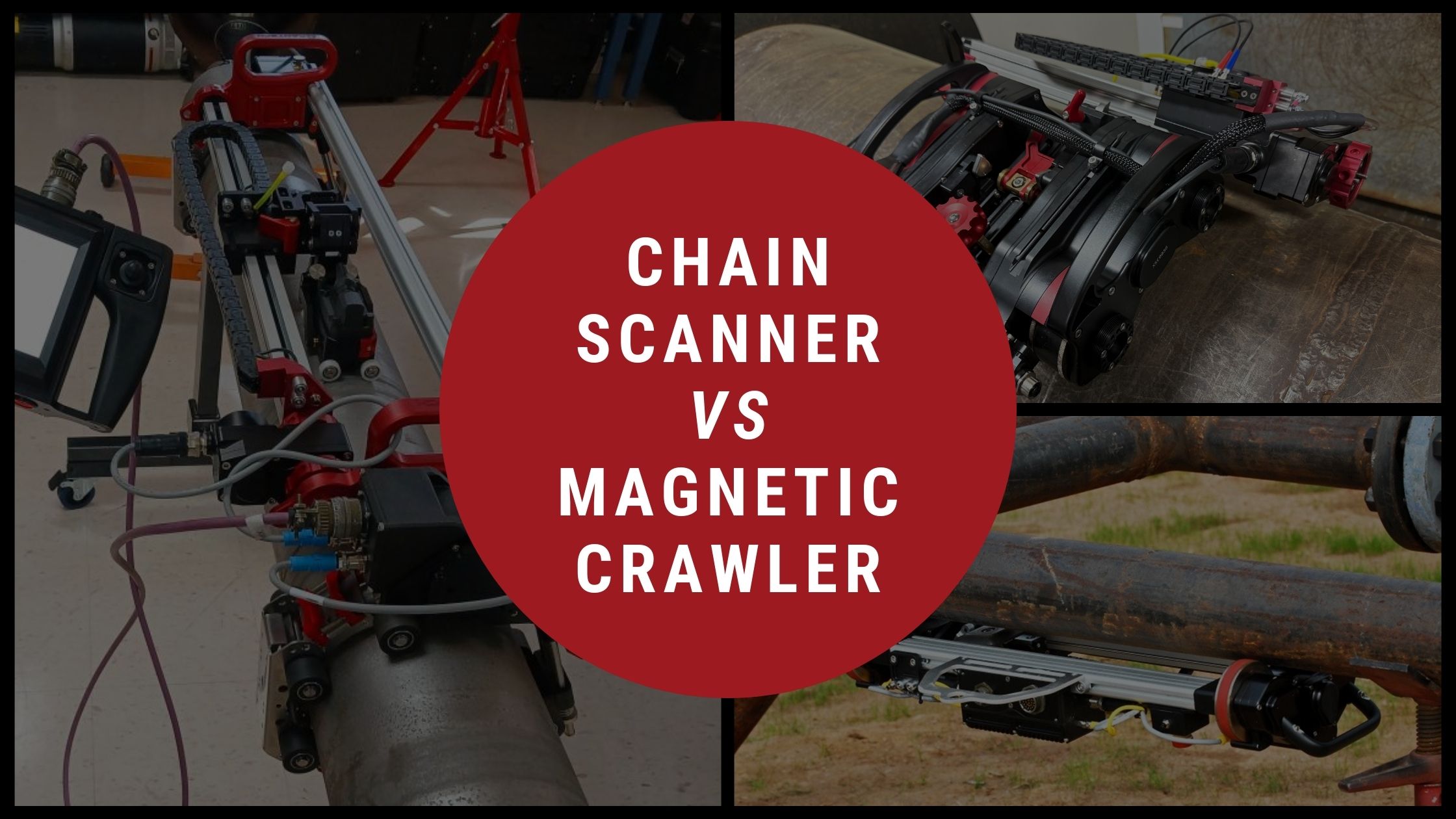
- Leverage automation: Automated and robotic scanning improves repeatability for complex surfaces.
For more examples of ultrasonic methods in industrial applications, see Weld Inspection with UT to compare defect detection approaches.
What to Do Next
Raising the Bar in Aerospace Safety
Ultrasonic testing in aerospace is both an art and a science. Success depends on the right combination of probe technology, coupling method, and interpretation skill.
By mastering these fundamentals, technicians ensure every inspection upholds the precision, safety, and reliability the aerospace industry demands.
To expand your understanding, revisit Ultrasonic Testing Basics and explore Single vs Dual vs Phased Array Probes for more on transducer selection and advanced UT techniques.