Table of Contents
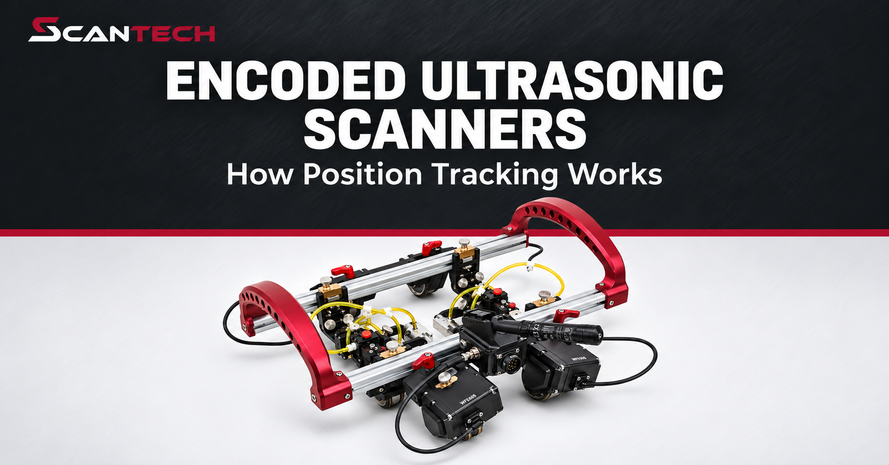
Encoded Ultrasonic Scanners: How Position Tracking Works
When you review an ultrasonic scan, the measurement needs a location. A thickness reading or weld indication becomes more useful when your team can connect it to a specific point along the inspection path.
Encoded ultrasonic scanners provide that position feedback. In a compatible inspection system, the instrument or software associates ultrasonic data with the scanner’s recorded position. An encoder can be attached to a probe assembly or scanning frame to track movement along the scan axis.
Understanding how encoding works helps you compare ultrasonic scanners and ask better questions before choosing equipment.
What Does “Encoded” Mean in Ultrasonic Testing?
An encoder measures movement along a defined path. Depending on the setup, it may use a wheel that follows the inspection surface or another position-tracking arrangement.
The encoder supplies position information. The ultrasonic instrument collects the inspection data. The system brings those two records together so readings can be reviewed against their location.
For example, an encoded weld scan can associate an indication with its distance from an established starting point. That gives the reviewer a position reference to use when examining the recorded scan.
Encoder arrangements vary. Wheel encoders depend on appropriate surface contact, while wire encoders use a different mechanical arrangement to track travel. The choice should suit the inspection geometry and instrument.
Can a Manual Ultrasonic Scanner Be Encoded?
Yes. Manual scanners can provide encoded position feedback.
With a manual encoded scanner, the technician moves the equipment while the encoder tracks travel. The operator supplies the movement, and the inspection system records position.
An automated encoded scanner uses motorized movement with position feedback. These are separate characteristics to evaluate when comparing equipment: how the scanner moves and how its position is recorded. Manual one-axis encoded scanners are established equipment configurations in ultrasonic testing.
Before deciding between them, consider what the job requires:
How much scanning is involved?
Can the operator maintain suitable access throughout the pass?
How often will the geometry or weld orientation change?
What position information must the instrument record?
A useful demonstration should address those questions using a configuration that resembles your work.
Why Position Tracking Matters in Weld Inspection
For weld inspection, start by defining the scan direction and the reference point.
Then look at how the scanner guides the probes and maintains their intended arrangement as it travels. Position feedback is one part of that setup. The mechanical frame, probe holders, and inspection technique also deserve attention.
Ask the demonstrator to show the scanner moving and the corresponding position readout. Then review the recorded data against that movement.
The RADIX modular weld inspection platform supports manual or automated operation for axial and circumferential weld scanning. Its manual configuration includes a surface-compensating encoder, and tool-free attachments support configuration changes.
When reviewing RADIX for an application, bring your weld orientation, pipe diameter, probe arrangement, and access requirements into the discussion.
How Encoding Supports Ultrasonic Corrosion Mapping
In ultrasonic corrosion mapping, thickness readings are associated with locations across a defined surface area. A C-scan presents those readings as a map of thickness variation.
That requires an understood relationship between the inspection data and the surface coordinates. A single line of readings and an area map provide different coverage information.
When evaluating a mapping setup, ask:
How is travel along each pass recorded?
How is the position of the next pass established?
What happens when the scanner is repositioned?
How does the software display the scanned area?
The arrangement depends on the equipment and inspection technique. Area mapping may use multiple motion axes or an indexing method that establishes the position between passes. Manual encoded mapping configurations can also use an indexing control.
For teams evaluating automated raster scanning, the XR corrosion mapping scanner provides multiple scan arm options and touchscreen or optional joystick steering. A demonstration is an opportunity to review those options alongside the intended inspection area.
What Can Affect Position Tracking?
Pay attention to the encoder’s mechanical connection to the inspection surface.
With a wheel encoder, contact and potential slippage matter. Position tracking arrangements that avoid wheel slippage illustrate why the encoder mechanism should be considered alongside the scanner itself. Probe coupling also requires the operator’s attention throughout the inspection.
Include these checks in your equipment discussion:
The encoder arrangement and its suitability for the surface.
The instrument’s encoder input and connection requirements.
The method for establishing the scan origin and direction.
The procedure for checking reported travel.
How the system handles indexing, stopping, and repositioning.
Ask the supplier to explain these points using the actual instrument and software you intend to operate.
What Should You Ask During an Ultrasonic Scanner Demo?
Watch the equipment operate, then review what the inspection system recorded.
These questions can help make the demonstration useful:
1. Can we see position feedback during a complete pass?
Follow the scanner’s movement and the displayed position together.
2. Can we review the data from that pass?
Ask how the software relates the inspection record to the scan location.
3. How does the setup change for our geometry?
Discuss diameter, scan direction, surface material, and surrounding obstructions.
4. What happens when scanning stops or the scanner is repositioned?
Have the demonstrator explain the workflow for continuing or repeating the inspection.
5. What is included in the proposed system?
Confirm the scanner configuration, encoder connection, controller, instrument compatibility, and software requirements before comparing quotes.
See How the Setup Fits Your Inspection
An equipment demonstration is most useful when it starts with the work your team performs.
Tell ScanTech what you inspect, the material and diameter, your inspection method, and any access restrictions. We can review scanner configurations and discuss the equipment around those requirements.
Request a ScanTech product demo.
Engineered from NDT for NDT.